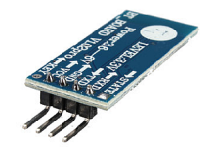
Bluetooth-Kommunikationsmodule
HC-05
Bluetooth ist ein drahtloser Kommunikationsstandard zur Überbrückung kurzer Entfernungen. Die Geräte sind im ISM-Band 2,4-2,485 GHz mit einer maximalen Übertragungsentfernung von etwa 10 Metern erhältlich. Das HC-05-Modul basiert auf dem 2,4-GHz-BlueTooth-Radio-Chip des Cambridge Silicon Radio BC417. Es ist ein komplexer Chip, der einen externen 8-Mbit-Flash-Speicher verwendet.
Merkmale der HC-nn-Serie
- Während der HC-05 sowohl als Master- als auch als Slave-Modul konfiguriert werden kann, kann der HC-06 nur als Slave verwendet werden
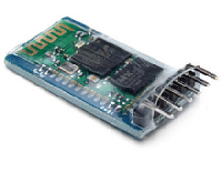
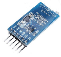
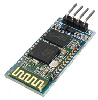
- Der HC-05 hat 6 Fuß und der HC-06 hat 4 Fuß
- Stellen Sie sicher, dass die Module normalerweise mit einer Versorgungsspannung von 3,3 V betrieben werden. Der 5V-Eingang ist vollständig modulabhängig.
- Die Module haben zwei Betriebsarten: AT Command -Modus / Normalmodus
- Oft wird das Modul selbst aufgerufen. vermarktet auf Breakout -Blättern. Diese haben keine Beine, nur Lötpunkte.
- Baudrate: 9600 bps, Daten: 8 Bit, Stop Bits: 1 Bit, Parität: Keine, Handshake: Keine
- Default Passwort: 1234
- Gerätenamen: HC-05 / HC-06
A HC-05 Pinbelegung
| Pin | Funktion |
|---|---|
| KEY | Befindet es sich vor dem Einschalten im Zustand HIGH, wird der Modus AT Command aktiviert. Die LED blinkt langsam (alle 2 Sekunden). |
| VCC | +5 Stromversorgung |
| GND | Grund |
| TXD | JÜbertragen von Signalen an das Arduino. 3,3 V Pegel! |
| RXD | Empfangen die serielle Daten von Arduino |
| STATE | Verbindung signalisiert |
"AT Command" -Modus
Es gibt zwei Möglichkeiten, den Befehlsmodus zu aktivieren
- Schließen Sie nach dem Einschalten der Stromversorgung des Moduls 5 V an den Anschluss KEY an. Auf das Modul kann dann im Befehlsmodus mit der voreingestellten Baudrate zugegriffen werden. Dies ist nützlich, wenn Sie Befehle von Ihrem Arduino senden möchten.
- Schließen Sie vor dem Einschalten der Stromversorgung des Moduls 5 V an den Anschluss KEY an. Das Modul wechselt dann in den 38.400-Baud-Befehlsmodus. Verwenden Sie das folgende Programm BlueToothCommandUtility zur Parametrisierung.
BlueToothCommandUtility
Schließen Sie das Modul wie folgt an das Arduino an:
- GND a GND-hoz
- Arduino Pin 2 zu HC-05 TXD
- Arduino Pin 3 zu HC-05 RXD
- Arduino Pin 4 zu HC-05 KEY
- Arduino Pin 5 + 6 zu HC-05 VCC-Stromversorgung
Das Programm:
/* YourDuino.com Example: BlueTooth HC-05 Setup
 - WHAT IT DOES:
   - Sets "Key" pin on HC-05 HIGH to enable command mode
   - THEN applies Vcc from 2 Arduino pins to start command mode
   - SHOULD see the HC-05 LED Blink SLOWLY: 2 seconds ON/OFF

 Sends, Receives AT commands
   For Setup of HC-05 type BlueTooth Module
   NOTE: Set Serial Monitor to 'Both NL & CR' and '9600 Baud' at bottom right
 - SEE the comments after "//" on each line below
 - CONNECTIONS:
   - GND
   - Pin 2 to HC-05 TXD
   - Pin 3 to HC-05 RXD
   - Pin 4 to HC-05 KEY
   - Pin 5+6 to HC-05 VCC for power control
 - V1.02 05/02/2015
   Questions: terry@yourduino.com */

/*-----( Import needed libraries )-----*/
#include <SoftwareSerial.h>
/*-----( Declare Constants and Pin Numbers )-----*/
#define HC_05_TXD_ARDUINO_RXD 2
#define HC_05_RXD_ARDUINO_TXD 3
#define HC_05_SETUPKEY        4
#define HC_05_PWR1            5  // Connect in parallel to HC-05 VCC
#define HC_05_PWR2            6  // Connect in parallel to HC-05 VCC

/*-----( Declare objects )-----*/
SoftwareSerial BTSerial(HC_05_TXD_ARDUINO_RXD, HC_05_RXD_ARDUINO_TXD); // RX | TX
/*-----( Declare Variables )-----*/
//NONE

void setup()   /****** SETUP: RUNS ONCE ******/
{
  pinMode(HC_05_SETUPKEY, OUTPUT);  // this pin will pull the HC-05 pin 34 (key pin) HIGH to switch module to AT mode
  pinMode(HC_05_PWR1, OUTPUT);      // Connect in parallel to HC-05 VCC
  pinMode(HC_05_PWR2, OUTPUT);      // Connect in parallel to HC-05 VCC

  digitalWrite(HC_05_SETUPKEY, HIGH);  // Set command mode when powering up

  Serial.begin(9600);   // For the Arduino IDE Serial Monitor
  Serial.println("YourDuino.com HC-05 Bluetooth Module AT Command Utility V1.02");
  Serial.println("Set Serial Monitor to 'Both NL & CR' and '9600 Baud' at bottom right");
  Serial.println("Vcc Power Up DELAY");
  delay(2000);
  Serial.println("Applying VCC Power. LED should blink SLOWLY: 2 Seconds ON/OFF");
  digitalWrite(HC_05_PWR1, HIGH); // Power VCC
  digitalWrite(HC_05_PWR2, HIGH);
  delay(2000);
  Serial.println("Enter AT commands in top window.");
  BTSerial.begin(38400);  // HC-05 default speed in AT command mode

}//--(end setup )---


void loop()   /****** LOOP: RUNS CONSTANTLY ******/
{
  // READ from HC-05 and WRITE to Arduino Serial Monitor
  if (BTSerial.available())
    Serial.write(BTSerial.read());

  // READ Arduino Serial Monitor and WRITE to HC-05
  if (Serial.available())
    BTSerial.write(Serial.read());

}//--(end main loop )---

/*-----( Declare User-written Functions )-----*/
//NONE

//*********( THE END )***********
Liste der Bluetooth AT-Befehle
1 AT Test UART Connection
2 AT+RESET Reset Device
3 AT+VERSION Querry firmware version
4 AT+ORGL Restore settings to Factory Defaults
5 AT+ADDR Query Device Bluetooth Address
6 AT+NAME Query/Set Device Name
7 AT+RNAME Query Remote Bluetooth Device’s Name
8 AT+ROLE Query/Set Device Role
9 AT+CLASS Query/Set Class of Device CoD
10 AT+IAC Query/Set Inquire Access Code
11 AT+INQM Query/Set Inquire Access Mode
12 AT+PSWD Query/Set Pairing Passkey
13 AT+UART Query/Set UART parameter
14 AT+CMODE Query/Set Connection Mode
15 AT+BIND Query/Set Binding Bluetooth Address
16 AT+POLAR Query/Set LED Output Polarity
17 AT+PIO Set/Reset a User I/O pin
18 AT+MPIO Set/Reset multiple User I/O pin
19 AT+MPIO? Query User I/O pin
20 AT+IPSCAN Query/Set Scanning Parameters
21 AT+SNIFF Query/Set SNIFF Energy Savings Parameters
22 AT+SENM Query/Set Security & Encryption Modes
23 AT+RMSAD Delete Authenticated Device from List
24 AT+FSAD Find Device from Authenticated Device List
25 AT+ADCN Query Total Number of Device from Authenticated Device List
26 AT+MRAD Query Most Recently Used Authenticated Device
27 AT+STATE Query Current Status of the Device
28 AT+INIT Initialize SPP Profile
29 AT+INQ Query Nearby Discoverable Devices
30 AT+INQC Cancel Search for Discoverable Devices
31 AT+PAIR Device Pairing
32 AT+LINK Connect to a Remote Device
33 AT+DISC Disconnect from a Remote Device
34 AT+ENSNIFF Enter Energy Saving mode
35 AT+EXSNIFF Exit Energy Saving mode
Bluetooth AT-Fehlercodes
0 Command Error/Invalid Command
1 Results in default value
2 PSKEY write error
3 Device name is too long (>32 characters)
4 No device name specified (0 length)
5 Bluetooth address NAP is too long
6 Bluetooth address UAP is too long
7 Bluetooth address LAP is too long
8 PIO map not specified (0 lenght)
9 Invalid PIO port Number entered
A Device Class not specified (0 lenght)
B Device Class too long
C Inquire Access Code not Specified (0 lenght)
D Inquire Access Code too long
E Invalid Iquire Access Code entered
F Pairing Password not specified (0 lenght)
10 Pairing Password too long (> 16 characters)
11 Invalid Role entered
12 Invalid Baud Rate entered
13 Invalid Stop Bit entered
14 Invalid Parity Bit entered
15 No device in the Pairing List
16 SPP not initialized
17 SPP already initialized
18 Invalid Inquiry Mode
19 Inquiry Timeout occured
1A Invalid/zero lenght address entered
1B Invalid Security Mode entered
1C Invalid Encryption Mode entered
Beispielprogramm HC-05
Ich habe das folgende Beispielprogramm von hier kopiert: http://www.instructables.com/id/Remotely-Control-LED-using-HC-05-Bluetooth-Arduino/
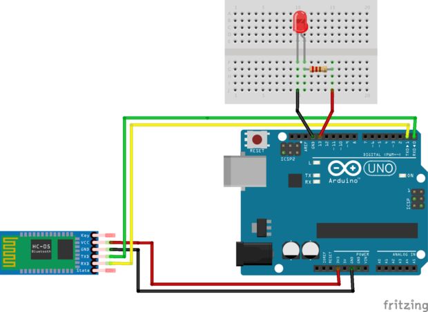
Erstens muss es verbunden werden
- Der VCC-Pin des Moduls mit dem 3,3-V-Ausgang des Arduino (nicht der 5-V!)
- Grund zu Grund
- Das Modul hat einen Rx-Fuß mit dem Arduino Tx-Fuß
- Das Modul hat einen Tx-Fuß mit dem Arduino Rx-Fuß
Das Beispielprogramm:
/*
Arduino Turn LED On/Off using Serial Commands
Created April 22, 2015
Hammad Tariq, Incubator (Pakistan)

It's a simple sketch which waits for a character on serial
and in case of a desirable character, it turns an LED on/off.

Possible string values:
a (to turn the LED on)
b (tor turn the LED off)
*/

char junk;
String inputString="";

void setup()                    // run once, when the sketch starts
{
 Serial.begin(9600);            // set the baud rate to 9600, same should be of your Serial Monitor
 pinMode(13, OUTPUT);
}

void loop()
{
  if(Serial.available()){
  while(Serial.available())
    {
      char inChar = (char)Serial.read(); //read the input
      inputString += inChar;        //make a string of the characters coming on serial
    }
    Serial.println(inputString);
    while (Serial.available() > 0)
    { junk = Serial.read() ; }      // clear the serial buffer
    if(inputString == "a"){         //in case of 'a' turn the LED on
      digitalWrite(13, HIGH);
    }else if(inputString == "b"){   //incase of 'b' turn the LED off
      digitalWrite(13, LOW);
    }
    inputString = "";
  }
}
Quellen
https://arduino-info.wikispaces.com/BlueTooth-HC05-HC06-Modules-How-To
http://www.instructables.com/id/Remotely-Control-LED-using-HC-05-Bluetooth-Arduino/


